

[F-16 Fighter Aircraft Operations Manual] 5. Engine Overview (Part 2): How to Start the Aircraft Engine
Release time: 2026-04-17
Let me briefly explain how the engine anti-icing system works
Anti-icing system
The anti-icing system directs low-pressure bleed air to the fixed inlet guide vanes and the internal passages of the engine cowling to prevent icing.
The system is controlled by a three-position anti-icing switch and can be activated manually or automatically via an icing detector located at the engine air intake. The air intake ducts are heated to prevent icing, with the heaters controlled centrally by the engine anti-icing switch.
Anti-freeze switch
The engine de-icing switch is located on the right-hand console. Its functions are as follows:
ON (On)
Activation of the electric heater for the intake support arm of the low-pressure bleed air guide fixed inlet vanes and the engine nose fairing
AUTO (Automatic)
When the icing detector detects engine icing (note that automatic detection may not be triggered during ground operations or when the angle of attack exceeds 7 degrees), it automatically activates the low-pressure bleed air supply to the fixed vanes and the cowl, whilst simultaneously activating the electric heaters on the intake booms.
OFF (Off)
When power is cut off, close the engine anti-icing valve (the valve remains open when power is cut off)
Switch off the intake manifold heater and the icing detectorWhen power is cut off, close the engine anti-icing valve (the valve remains open when power is cut off)
Switch off the intake manifold heater and the icing detector
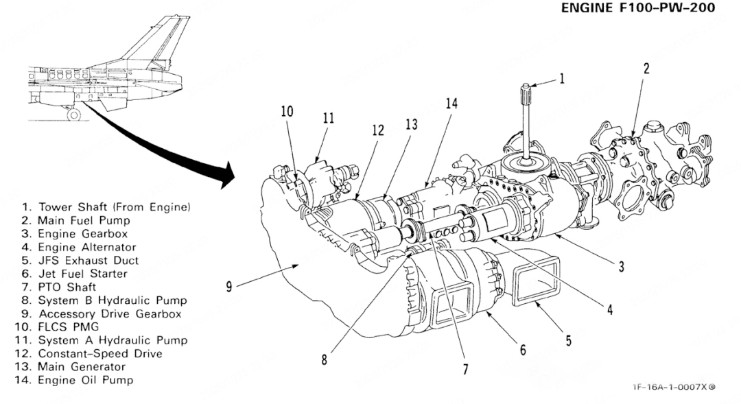
Engine accessory gearbox
As shown in the figure:
1.Tower Shaft
2.Main Fuel Pump
3.Engine Gearbox
4.Engine Alternator
5.JFS Exhaust Duct
6.Jet Fuel Starter
7.PTO Shaft (Power Take-Off Shaft)
8.System B Hydraulic Pump
9.Accessory Drive Gearbox
10.FLCS PMG
11.System A Hydraulic Pump
12.Constant-Speed Drive
13.Main Generator
14.Engine Oil Pump
The engine gearbox drives the main fuel pump, the lubricating oil pump assembly, the engine alternator and the power take-off shaft, which provides power to the auxiliary gearbox.
The auxiliary gearbox drives the main generator via a constant-speed drive, whilst also driving the A/B system hydraulic pumps and the flight control system’s permanent magnet generator; the jet fuel starter is also mounted on this gearbox.
Engine ignition system
The ignition system is powered by the engine alternator and comprises three ignition coils (two for the main engine and one for the afterburner). When the throttle lever is in the idle or higher position and the engine speed reaches 15% or above, the main engine will remain in continuous ignition mode. When the throttle lever is pushed into the afterburner range, afterburner ignition will be activated for approximately 1 second. To initiate afterburner ignition again, the throttle must first be reduced to military power (MIL) or below and held there for at least 1.5 seconds, before being pushed back into the afterburner range.
Jet fuel starter
The Jet Fuel Starter (JFS) is an aviation fuel-powered gas turbine that drives the main engine via the Auxiliary Drive Gearbox (ADG). The JFS is connected to the ADG via a clutch and provides torque only when required to maintain engine speed. If the ADG cannot rotate (e.g. due to engine seizure), the JFS can continue to operate whilst the clutch prevents it from driving the ADG. The JFS is always supplied with fuel, regardless of the position of the main fuel switch.
The JFS is powered by two brake/JFS accumulators, which can operate individually or in conjunction. These accumulators can be charged automatically via the B hydraulic system or manually using the hydraulic hand pump in the left wheel well. The automatic charging time ranges from 40 seconds (in high-temperature conditions) to 60 seconds (in low-temperature conditions). The JFS is used for ground engine start-up and as an auxiliary for in-flight start-up.
Engine and Jet Start Control Panel
As shown in the figure:
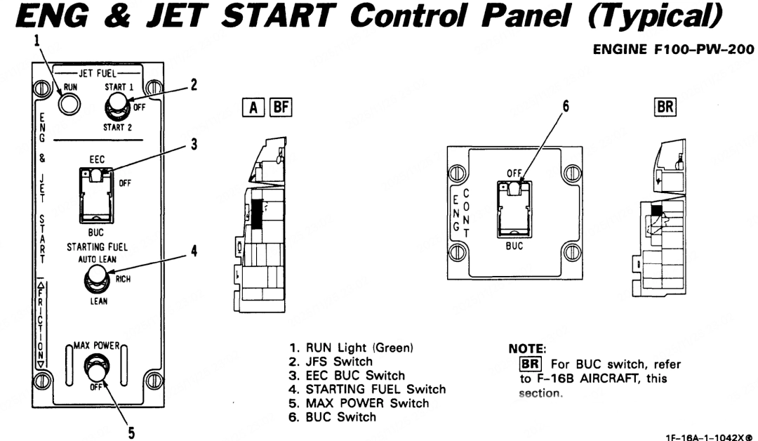
The engine start panel is located on the left-hand console
Item 1 is the start-up indicator light (green). The green JFS start-up indicator light illuminates within 30 seconds of the start command being issued, indicating that the jet fuel starter has reached the operating speed controlled by the governor.
Item 2 is the start switch:
OFF (Off) Standard switch position. Selecting OFF will deactivate the JFS at any time. During a normal ground start, when the engine speed reaches 50%, the switch will automatically return to the OFF position.
START 1 (Start 1) Releases hydraulic fluid from a single brake/JFS accumulator to the hydraulic start motor. Application: Standard ground start / ambient temperature conditions
START 2 (Start 2) Simultaneously releases hydraulic fluid from both brake/JFS accumulators to the hydraulic starter motor.
Applications: Start-up in low-temperature environments / emergency start-up / start-up when the accumulator pressure is insufficient.
During ground start-up, the brake/JFS accumulator begins to pressurise automatically when the engine speed exceeds 12%. When the engine speed exceeds 50%, a sensor triggers the automatic shutdown of the JFS, and the JFS indicator light goes out.
During flight operations, the accumulator begins to pressurise when the JFS reaches 70% of the speed control speed (this process occurs 3–4 seconds before the JFS indicator light illuminates), provided that hydraulic pressure in System B is available.
If the JFS operation indicator light does not illuminate within 30 seconds, or if it illuminates and then unexpectedly goes out, the JFS start switch will remain locked. The system must not be restarted until the JFS rotor has come to a complete standstill (this takes approximately 17 seconds from rated speed to a complete stop).
Once the JFS has started running, it will continue to operate until its switch is manually set to the OFF position.
Item 6 is the Electronic Engine Control – Backup Control Switch (EEC BUC) (with protective cover; defaults to the BUC position) located on the left-hand console.
Its functions are defined as follows:
EEC position: Electronic Engine Controller is active (normal operating position)
OFF position: EEC disabled (switches to basic hydraulic-mechanical operation via the Combined Fuel Controller)
BUC position: Backup fuel control enabled. Switching conditions: The throttle lever is in the OFF position, or is at or above the BUC idle position. To trigger the switch, it may be necessary to move the throttle lever past the BUC idle position.
