
[F-16 Fighter Aircraft Operations Manual] 4. Engine Overview (Part 1)
Release time: 2026-04-12
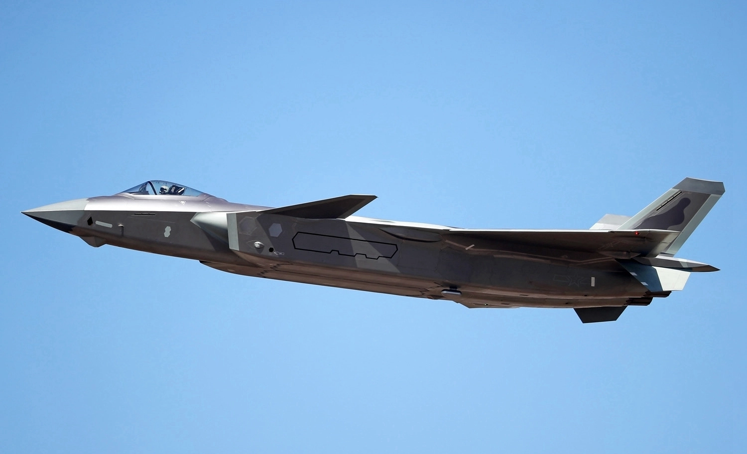
The aircraft is powered by a single F100-PW-200 afterburning turbofan engine, with a maximum thrust of approximately 25,000 pounds, or about 11.34 tonnes.
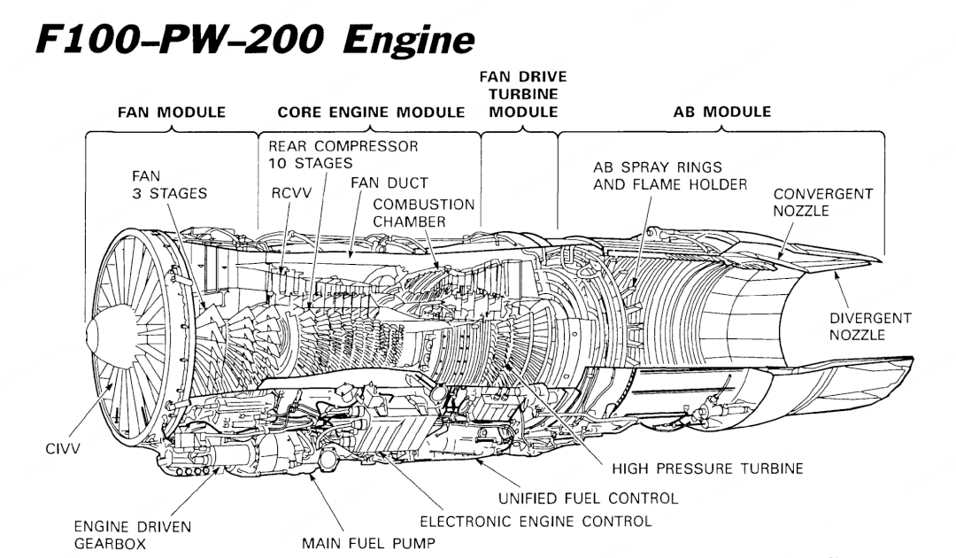
The translations of the names of the various positions are as follows:
FAN MODULE
This is the foremost core component assembly of modern high-bypass-ratio turbofan engines, forming the engine’s air intake and primary propulsion system. The module draws in the vast majority of the airflow via a single-stage or multi-stage large-diameter fan, diverting it to the core (inner bypass) and outer bypass, and directly determines the engine’s thrust, efficiency and noise levels.
The three-stage fan shown in the diagram comprises a low-pressure rotor front-end module consisting of three consecutive fan/compressor stages. These three sets of rotor blades work in conjunction with the corresponding stator blades to draw in and compress air in successive stages.
CORE ENGINE MODULE (Core modules)
RCVV (Rear Compressor Variable Vane)
Static vanes are installed in the first few stages of the engine’s high-pressure compressor; the installation angle of these vanes can be adjusted according to the engine’s operating conditions. By rotating the vanes, it is ensured that, at different rotational speeds, the airflow entering the first-stage high-pressure compressor rotor blades strikes the blades at the optimum angle of attack, whilst also preventing surging.
REAR COMPRESSOR 10 STAGES (Stage 10 rear compressor)
A high-pressure compressor module located between the fan or low-pressure compressor and the combustion chamber, comprising 10 consecutive compression stages. Its function is to compress air to the extremely high pressure required for combustion.
COMBUSTION CHAMBER (Combustion chamber)
Through continuous, steady combustion, the chemical energy of the fuel is converted into the thermal and pressure energy of high-temperature combustion gases.
FAN DRIVE TURBINE MODULE (Fan-driven turbine module)
Energy is extracted from the high-temperature, high-pressure gas discharged from the core unit and converted into mechanical work that drives the rotation of the fan (and the low-pressure compressor).
AB MODULE(Afterburner module)
Its core function is to inject and burn fuel within the high-temperature exhaust gases emitted by the engine, thereby dramatically increasing the engine’s thrust for a short period.
HIGH PRESSURE TURBINE(High-pressure turbine)
A set of turbines mounted on the high-pressure rotor downstream of the combustion chamber. Their primary function is to extract energy from the hottest, highest-pressure exhaust gases leaving the combustion chamber, which is then used to drive the high-pressure compressor at the front of the engine.
UNIFIED FUEL CONTROL (UFC) -Combined Fuel Controller
ELECTRONIC ENGINE CONTROL – Engine control unit
MAIN FUEL PUMP – Engine control unit
ENGINE DRIVEN GEARBOX – Engine-driven gearbox
The main engine is controlled by a hydraulic-mechanical combined fuel control unit (UFC). This UFC integrates engine fuel control, afterburner fuel control, rear compressor variable vane (RCVV) and start bleed air control, as well as convergent nozzle area control functions.
UFC
The Unified Fuel Controller (UFC) calculates the base engine fuel flow based on throttle lever position, rear compressor rotor speed, turbine inlet temperature (FTIT) and combustion chamber pressure parameters. The fuel delivery from the UFC is fine-tuned by the Electronic Engine Controller (EEC), which modifies the fuel flow based on fan speed, engine intake temperature and turbine inlet temperature (FTIT). Although the afterburner fuel flow is set by the UFC, the EEC can impose flow limitations via the fifth-stage afterburner lock and surge recovery logic functions.
EEC
The Electronic Engine Controller (EEC) is a solid-state digital computer mounted on the engine and cooled by fuel. The EEC fine-tunes the engine’s fuel flow and convergent nozzle area by sending commands to the Unified Fuel Controller (UFC). This controller is fully responsible for the control logic of the Compressor Inlet Variable Vanes (CIVV) and provides signal inputs to the UFC for engine surge recovery, fifth-stage afterburner lockout, afterburner ignition suppression and idle-speed reset.
The Electronic Engine Controller (EEC) uses a closed-loop idle control mode to fine-tune the idle fuel flow from the Unified Fuel Controller (UFC) in real time, in order to maintain a preset fan speed. This control mechanism provides constant and reproducible idle thrust in both flight and ground conditions. When the throttle lever is in or near the idle position and the landing gear lever is in the down position, the system issues a command to open the nozzles to reduce the idle thrust level.
The electronic engine controller continuously limits the engine to its minimum operating state across the entire flight envelope to ensure stable operation
At high altitudes and low airspeeds, the EEC prevents engine surging caused by low thrust conditions.
During transonic and supersonic flight, the EEC uses a mathematical function based on the Mach number signal from the Central Atmospheric Data Computer (CADC) to limit the engine’s minimum operating conditions, thereby ensuring sufficient engine air intake flow.
To minimise the risk of engine surge when afterburner is engaged at high altitudes and low airspeeds, the Electronic Engine Controller (EEC) will forcibly terminate fuel supply to the fifth stage of the afterburner. Should engine surge occur whilst the afterburner is engaged, the EEC will automatically switch the engine to minimum afterburner fuel flow, regardless of the throttle lever position.
In non-afterburner conditions, the EEC’s surge recovery logic operates most effectively when the throttle is set to the military power (MIL) position: at this point, the EEC instructs the Unified Fuel Controller (UFC) to open the nozzle to eliminate the excessive backpressure caused by the surge. All of the above protective functions are automatically deactivated when the EEC is switched off.
If the engine fan overspeeds, the Electronic Engine Controller (EEC) will automatically shut down and trigger the EEC warning light to illuminate. In this situation, the EEC cannot be reset. The EEC is powered directly by the engine alternator. If a fault occurs in the engine alternator or engine gearbox (manifested by a sudden drop in speed to zero and the engine warning light illuminating), the EEC will cease to function; in this instance, the EEC warning light may not illuminate. Within specific limits, the engine may continue to operate without the EEC.
Standby fuel control system BUC
The Backup Fuel Control (BUC) system is a hydraulic-mechanical assembly that takes over engine control in the event of a failure of the Unified Fuel Control (UFC) system. The system is manually activated via the BUC switch on the Electronic Engine Control (EEC) panel, and its fuel flow regulation is based solely on two parameters: the throttle lever position and the static pressure in the engine fan duct (used for altitude compensation).
Main Fuel Pump and Afterburner Fuel Pump The main fuel pump, mounted in the gearbox, is responsible for supplying pressurised fuel to the engine and providing pressure boost to the afterburner fuel pump. The afterburner fuel pump is driven by engine bleed air and supplies pressurised fuel to the afterburner stage of the Unified Fuel Control (UFC). This pump also provides the power source for the hydraulic actuators of the compressor inlet variable vanes (CIVV), rear compressor variable vanes (RCVV) and the start bleed air actuator.
Compressor bleed air
Low-pressure (stage 7) bleed air is drawn from the bleed ring into the fan duct to increase the compressor surge margin during engine start-up. This bleed valve is actuated by the Unified Fuel Controller (UFC) using pressurised fuel supplied by the afterburner fuel pump; in Backup Fuel Control (BUC) mode, it is activated by the throttle lever position. The low-pressure bleed air is also used for the engine inlet anti-icing system.
High-pressure (13th stage) bleed air supplies the Emergency Power Unit (EPU) and the engine nacelle injectors, whilst also being used to drive the afterburner fuel pump and the core engine electronic control unit (CENC) motor.
Depending on the engine bleed air pressure level, the Environmental Control System (ECS) can receive either low-pressure or high-pressure bleed air.