

[F-16 Fighter Aircraft Operations Manual] 9. Landing Gear Operations
Release time: 2026-05-15
The landing gear control panel and buttons are located at the top of the left-hand console, as shown in the figure:
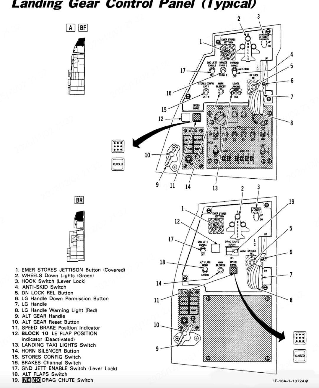
1、EMER STORES JETTISON Button
2、WHEELS Down Lights (Green)
3、HOOK Switch (Lever Lock)
4、ANTI-SKID Switch
5、DN LOCK REL Button
6、LG Handle Down Permission Button
7、LG Handle
8、LG Handle Warning Light (Red)
9、ALT GEAR Handle
10、ALT GEAR Reset Button
11、SPEED BRAKE Position Indicator
12、LE FLAP POSITION Indicator
13、LANDING TAXI LIGHTS Switch
14、HORN SILENCER Button
15、STORES CON FIG Switch
16、BRAKES Channel Switch
17、GND JETT ENABLE Switch (Lever Lock)
18、ALT FLAPS Switch
19、RAG CHUTE Switch
When either the nose landing gear or the main landing gear is not in the lowered and locked position, and all of the following conditions are met, the landing gear warning buzzer will sound intermittently through the headphones:
Airspeed below 190 knots
Altitude below 10,000 feet
Rate of descent greater than 250 feet per minute
Press the landing gear warning buzzer mute button to silence the landing gear warning buzzer. If the condition triggering the warning is resolved, the buzzer will automatically reset; if the condition persists, subsequent landing gear voice warnings will not be triggered.
Take-off/Landing Configuration Warning Light is located on the left sun visor and illuminates during flight if all of the following conditions are met:
Altitude below 10,000 feet
Airspeed below 190 knots
Rate of descent greater than 250 feet per minute
and any of the following conditions applies:
1、Flaps not fully extended (TEF’s not fully down)
2、Nose landing gear or either main landing gear not extended and locked (accompanied by landing gear warning buzzer)
Ground status: If the flaps are not fully extended, the warning light will also come on.
Special note: When the flaps are fully extended, if the aforementioned conditions regarding altitude, airspeed and rate of descent are met (or if the wheel load signal is triggered), a sudden roll control input may cause this warning light to illuminate momentarily.
Landing gear down indicator lights These three green landing gear down indicator lights are located on the landing gear control panel, arranged in the shape of an aircraft.
When any main landing gear is extended, the corresponding indicator light illuminates. When all three indicator lights and the landing gear lever warning light are off, the landing gear is in a safe, retracted and locked position. This indicator light system is powered by the battery busbar (or individual battery busbars) – with the exception of certain aircraft types (to energise the lock-down relay) – and the No. 1 critical DC busbar (for indicator light illumination).
Landing gear operation
Moving the landing gear lever to the UP (retracted) position triggers the following sequence of actions:
1、The landing gear handle warning light illuminates
2、The landing gear unlocks and begins to retract
3、The three green ‘WHEELS’ down indicators go out
4、The main landing gear wheels stop rotating (brakes applied)
5、Landing gear doors close and lock
6、Landing gear handle warning light goes out
7、Hydraulic system stops supplying pressure to the landing gear
8、Flight control system (FLCS) switches to cruise gain mode
9、Flaps retract to streamlined position (TEF retracted)
10、Power to brake channel 1 is disconnected
11、Nozzle management programme activated whilst landing gear is retracted
Moving the landing gear lever to the DN (Down) position triggers the following sequence of actions:
1、The landing gear warning light comes on
2、The landing gear doors open, landing gear unlocked, extended and locked in position
3、Three green WHEELS down indicators illuminate
4、Landing gear handle warning light extinguishes
5、Flaps (TEF) extended
6、Flight Control System (FLCS) switches to Take-off/ landing gain mode
7、The nozzle scheduler is activated whilst the landing gear is extended
8、The speed brakes are automatically retracted to 43° (unless manually overridden)
9、Power is restored to brake channel 1
![[F-16 Fighter Aircraft Operations Manual] 2. General Layout and Basic Specifications](https://lingjuimg.com/wp-content/uploads/daliangzest/2026/03/首图.webp)

