

[F-16 Fighter Aircraft Operations Manual] 6. Throttle Lever, Throttle and Engine Surge
Release time: 2026-04-24
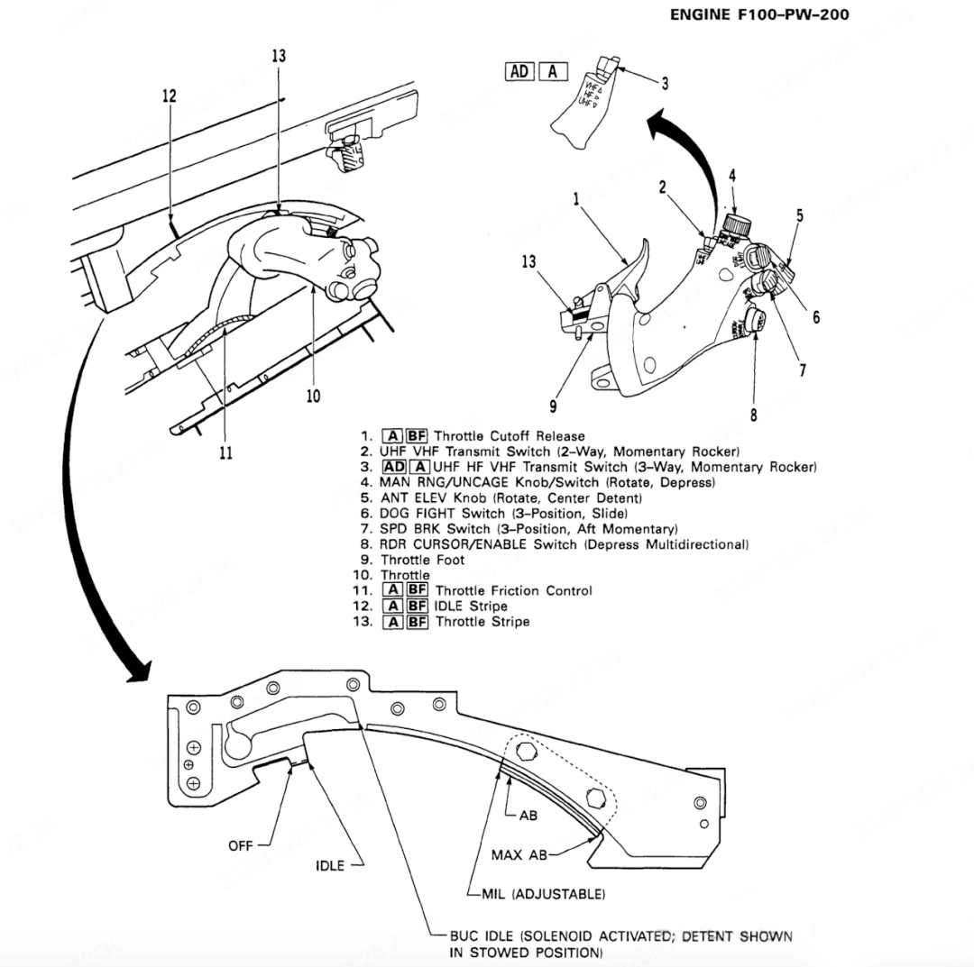
The throttle lever is located on the side of the left-hand console. Unlike the throttle in a car or on a motorbike—where the car’s throttle is operated by the foot and the motorbike’s by twisting the right hand—the F-16’s throttle is operated by pushing it with the hand.
Throttle lever
1. Throttle Cutoff Release Mechanism
It is a mechanical safety lock, typically located between the idle and closed positions of the throttle lever. Its primary function is to prevent the throttle lever from being inadvertently pushed directly from the ‘closed’ position to a position beyond ‘idle’, or from a position beyond ‘idle’ being inadvertently pulled back to the ‘closed’ position. Operating it requires the pilot to perform a deliberate, additional action.
2.UHF VHF Transmit Switch
Its core function is to allow pilots to switch transmission channels quickly between UHF and VHF radio modes without taking their hands off the control stick.
3. UHF/HF/VHF transmitter selector switch
Its core function is to allow pilots to switch transmission channels rapidly between UHF, HF and VHF radio modes, enabling full-spectrum tactical communications without taking their hands off the control stick. Pilots select the desired band using a thumb-operated switch and, by simultaneously pressing the microphone button on the control stick, can transmit voice communications via the corresponding radio. The switch is typically momentary; upon release, it automatically returns to the centre position whilst retaining the selected band.
4. MAN RNG/UNCAGE Knob/Switch (Rotate, Depress)
A high-performance composite controller within the weapon control system. It physically integrates target parameter settings (range) with tactical manoeuvre execution (unlocking) into a single control, enabling the pilot to complete the aiming and attack sequence in the most direct and rapid manner during the fast-paced dynamics of aerial combat. In the case of early infrared-guided missiles, pressing the ‘UNCAGE’ button would cause the missile’s seeker to begin autonomously searching for and tracking heat sources (targets) within its field of view.
5. ANT ELEV Knob (Rotate, Center Detent)
It is a rotary controller with a central detent, used to manually control the vertical scanning pitch angle of a radar or other electronic warfare antenna.
6. DOG FIGHT Switch (3-Position, Slide)
It is a three-position toggle switch designed specifically to rapidly switch the weapon systems, radar and displays to a pre-set, optimised air-to-air combat mode during close-range aerial combat (dogfights), thereby minimising operational complexity and enhancing reaction times.
7. SPD BRK Switch (3-Position, Aft Momentary)
It is a three-position switch with a rear-position momentary function, used to control the deployment and retraction of the aircraft’s speed brakes. Speed brakes are control surfaces hinged to the fuselage or wings of an aircraft; when deployed, they significantly increase the aircraft’s drag, thereby enabling rapid deceleration, descent or energy dissipation.
8. RDR CURSOR/ENABLE Switch (Depress Multidirectional)
It is a push-button, multi-directional joystick switch that integrates two core functions: radar cursor movement and mode activation/selection. It is one of the most important human-machine interfaces in the radar and sensor management systems of modern fighter aircraft.
9. Throttle Foot
10. Throttle lever
11. Throttle Friction Control
It is a mechanical adjustment device, usually a knob or lever, used to increase or decrease the force required for the pilot to push the throttle lever forwards or backwards.
12. IDLE Stripe: Indicates the throttle lever position for idle13. Throttle Stripe: Indicates the idle, military thrust and afterburner ranges
Throttle and engine
During flight or ground operations, low-frequency engine vibrations may be felt when the engine is idling or approaching idle speed; such vibrations may also occur at higher thrust levels. These vibrations have no adverse effect on the engine or the aircraft structure, and they usually disappear as the engine speed increases or decreases.
However, if the intensity of the vibration varies with throttle position and persists across the entire throttle/RPM range, this may indicate a potential engine fault. The engine’s operating condition is continuously optimised in response to changing flight conditions, as evidenced by subtle changes in nozzle position, RPM and the turbine inlet temperature indicator.
Below an altitude of approximately 10,000 feet (3,000 metres), the idle speed should always be equal to or slightly higher than the ground idle speed. As altitude increases, the idle speed should be raised accordingly to ensure that the engine maintains sufficient surge margin during throttle transients.
When the Mach number reaches 1.4 or higher, the engine will maintain military power as the minimum thrust reference even if the throttle lever is retracted below military power (MIL). Typically, the minimum thrust level will gradually increase from idle to military power within the Mach 0.84 to 1.4 range. All minimum thrust limitation functions are automatically disabled in SEC (Special Emergency Control) mode.
Low-frequency engine vibrations may occur during flight or on the ground, primarily at low engine speeds, though they may also occur at higher thrust settings. Such vibrations have no adverse effect on the engine or the aircraft structure, and typically disappear when the engine speed is increased or decreased. If the intensity of the vibrations continues to vary with throttle movement and persists across the entire throttle/engine speed range, this may indicate a potential engine fault.
Thrust control
In boost mode, the Digital Engine Electronic Control (DEEC) system provides the following functions:
1. Rapid acceleration capability
There are no restrictions on the afterburner during the transient process from idle to full afterburner:
- Height above sea level: Start immediately after selecting boost
- High-altitude mode: The fan must first reach a higher speed before it can start. Comparison example:
- From low-thrust idle to maximum afterburner: the afterburner ignites when thrust is slightly higher than idle, with the entire process taking approximately 4 seconds
- From low-altitude cruise to maximum thrust: the entire process takes approximately 11 seconds
2. Redistribution of boost fuel flow
During low-speed flight at high altitude, the system redirects fuel flow from the fifth stage to the third stage in order to maintain afterburner stability.
3. Analysis of the system control logic:
- Adaptive ignition strategy
- Low altitude: Direct ignition (using air density to achieve stable combustion)
- High altitude: Delayed ignition (requires a higher accumulation of core engine energy to ensure combustion efficiency)
- Dynamic fuel allocation
- Fault prevention: Suppressing combustion oscillations by redistributing fuel from Zone 5 to Zone 3
- Stability assurance: prioritising flame stability over maximum thrust
- Wrap-around protection mechanism
- The difference in time thresholds (4 seconds vs 11 seconds) demonstrates the DEEC’s real-time compensation for intake conditions
- Continuous surge monitoring: predicting instability by tracking changes in compressor outlet pressure in real time
4. Sequence restrictions for power-up sections
When afterburner is selected at very high altitudes and low speeds, the system will only plan for Stage 1 afterburner. If the aircraft has already entered this airspace with afterburner set to a level higher than Stage 1, the system will maintain the current setting. When Stage 2 or higher afterburner is selected within this airspace, the engines will automatically and sequentially increase to the requested throttle position once the aircraft has exited this airspace.
5. Boost cycle capability
The DEEC works in conjunction with the limiter detection unit (LOD) to provide an automatic boost cycle function:
- Trigger condition: Afterburner active / not ignited (throttle held in afterburner position)
- Automated process:
- Reset the control system to military (MIL) power settings
- Perform a self-test on the control system
- Up to three ignition attempts
- Automatically revert to MIL mode following a failure
- LOD failure mode: Switch to using the pipe pressure signal to verify ignition; perform only one retry
- No warning message: A failed afterburner cycle does not trigger the warning light
- Manual retry: Reduce throttle to MIL or below, then return to the afterburner zone

