The ultimate in sensory simulation demands meticulous system operation to achieve.
Refuse to fly blind. This column distils core data from the original F-16 manual, stripping away superfluous information to reveal the cockpit’s interactive logic, empowering you to master this full-motion simulator.
This issue covers a great deal of content, primarily detailing the engine control unit and associated gauges on the instrument panel.
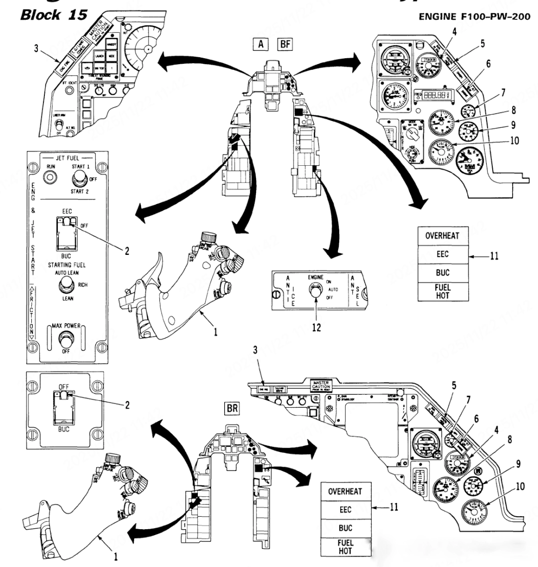
As core components of the flight control interface, these control and indication units are distributed across the cockpit’s operating panels in accordance with aviation ergonomic principles. Together with the fuel system, starting system, and anti-icing system, they form a comprehensive engine monitoring system.
- Throttle lever
The primary control device within the aircraft cockpit for infinitely variable adjustment of engine thrust output. Its angular displacement actuates the fuel control assembly via steel cables or fly-by-wire systems, enabling seamless transitions from idle to military thrust to afterburner modes. The lever integrates multifunctional controls including radio transmit buttons and trim switches, meeting the 17° operating travel and 8-22 lb operating force requirements specified in the MIL-STD-1472G human-machine interface standard.
2. [A] [BF] EEC BUC; [BR] BUC switch. The backup fuel control mode selector on the engine electronic control unit.
3. Engine Fire Warning Light (Red) When the continuous annular fire detector within the engine nacelle detects overheating or flame signals, it activates a dual-channel alarm circuit to illuminate the red warning light continuously. Concurrently, this triggers the engine fire suppression system to enter standby mode.
4. Fuel Flow Indicator Used to display in real time the mass flow rate of fuel entering the combustion chamber per unit time (typically measured in pounds per hour or kilograms per hour). Its sensor measures the pressure differential across the fuel metering valve and the fuel density, which is then processed by the Electronic Engine Control (EEC) to drive either an analogue pointer or digital display unit. This reading, when combined with the RPM indicator, enables rapid assessment of engine operating conditions. It serves as a critical reference for monitoring fuel efficiency, identifying abnormal consumption, and diagnosing fuel system faults. The indication range typically covers the entire envelope from idle to maximum throttle, with accuracy meeting the ±2% error tolerance specified in the MIL-M-7793D military standard.
5. Hydraulic/Lubricating Oil Pressure Warning Light (Red) The red warning light will illuminate when any of the following conditions occur:
- Hydraulic system pressure below 2150 ± 150 psi (System A/B)
- The lubricating oil system pressure deviates from the 8-25 psi operating range.
- Abnormal lubricating oil filter pressure differential (ΔP ≥ 25 psi) Its dual-parameter monitoring architecture employs dual verification via pressure switches and the EEC’s ARINC 429 data bus. Upon warning activation, immediately verify the corresponding system’s pressure indications and temperature parameters, and execute emergency procedures in accordance with MIL-STD-1299 ‘Aircraft Powerplant Monitoring Requirements’.
6. Engine warning light (red)
7. Oil Pressure Gauge This instrument serves as a critical monitoring device for the engine lubrication system, displaying real-time pressure within the main oil circuit (typically measured in psi or kPa). Its sensor gauges pressure at the gear pump outlet, transmitting readings via mechanical lines or electrical signals to the cockpit indicator. Under normal operation, pressure should remain within the 15-25 psi range (typical values), increasing with rising engine speed. However, vigilance is required for the following abnormal conditions:
- Pressure < 8 psi: Trigger LOW OIL PRESS warning
- Pressure drop: Indicates pump failure or bearing pressure relief
- Pressure oscillation: Indicates cavitation in the oil circuit This indicator serves as the primary basis for assessing engine health, with its readings requiring cross-verification against lubricant temperature and oil level indicators.
8. Tachometer (This instrument serves as the core indicator for engine power status, monitoring the mechanical rotational speed of the rotor system in real time. It typically employs a dual-pointer or dual-display digital configuration:
- N1 gauge: Displays low-pressure rotor speed (fan speed), determining the primary thrust of the engine.
- N2 gauge: Displays high-pressure rotor speed (core unit speed), linked to the fuel control system. Its sensor utilises a magnetic-electric probe to capture gear tooth pass frequency, which the EEC converts into percentage speed (100% corresponding to the maximum continuous design speed). Key reading ranges include:
- Slow-speed gear status: N1 approximately 20-30%, N2 approximately 50-60%
- Military thrust status: Both rotors approaching 100%
- Over-rev warning: N1 > 105% or N2 > 108% sustained for 0.5 seconds This instrument reading must be interpreted in conjunction with fuel flow and EGT parameters, serving as the primary basis for assessing engine power output and mechanical integrity.
9. Nozzle Position Indicator (This instrument monitors variations in nozzle area, typically displaying the real-time percentage opening of the convergent nozzle. Its sensor converts mechanical position into a linear indication of 0-100% by analysing the displacement signal from the CENC actuator, where 0% corresponds to minimum area and 100% to maximum area.) Typical readings include:
- Slow speed condition: 70-95% (landing gear down)
- Cruising condition: 35-50% (landing gear retracted)
- Afterburner status: Increases progressively with throttle application. This indicator forms a triad with the EGT and tachometer for afterburner system monitoring. Abnormal positional vibration may indicate hydraulic failure in the CENC system or mechanical jamming of the nozzle.
10. Inter-Turbo Temperature Indicator This instrument serves as a critical device for monitoring the engine’s thermal load, measuring the static temperature within the gas passage between the high-pressure and low-pressure turbines. Its sensor employs a K-type thermocouple array, transmitting the thermoelectric potential signal via compensation leads to the Engine Electronic Control (EEC) unit for cold junction compensation and linearisation processing. The final display unit is degrees Celsius. Typical reading range:
- Slow-cooking temperature: 400–600°C
- Maximum military thrust: 950–1050°C
- Over-temperature warning: ≥1100°C (Persistent exceedance will trigger automatic thrust reduction) This indicator serves as a core parameter for assessing turbine blade lifespan and evaluating combustion efficiency, requiring trend correlation analysis with fuel flow and nozzle position. Abnormal temperature rise may indicate fuel distributor malfunction or impaired turbine cooling airflow.
11. Warning Light (Amber) (This level of illumination indicates non-emergency abnormal conditions requiring pilot attention but not immediate control action. Its amber light source conforms to the chromaticity coordinates (x=0.571, y=0.429) of MIL-STD-1472H, with a brightness adjustable range of 3-50 feet-lambs. Trigger logic includes:
- System performance degradation (e.g. generator feeder failure)
- Preventive maintenance alerts (e.g. oil filter nearing blockage)
- Configuration warning (e.g. hatch not latched)
- The backup system activation, combined with the red warning light, forms a two-stage alerting system requiring the pilot to identify the status within 15 seconds and take appropriate action at the appropriate time. The light remains illuminated until the fault condition is resolved or the primary warning reset is performed.